
47 GHz TRV 2nd. gen and RX performance test
Measurement results 27/05/2025
Sun - 11,5 dB - Moon 1,6dB
Lately, I've been spending a lot of time working on EME in the 47 GHz band. It's a technological and technical challenge that has kept me awake for many years. In 2020, I made my first attempt at receiving in the 47 GHz band, and it didn't turn out very well. In fact, I felt exactly the same as when I switched from 10 GHz to 24 GHz. The first feeling was one of disappointment and wasted investment. I had to go back to square one and start from scratch, just as I had done with the lower bands. However, the 47 GHz band has its pitfalls in that, unlike the lower bands, I had the opportunity to consult with the EME community in OK, where OK1KIR and OK1CA are still world leaders. I had to learn the 47 GHz band “abroad.” In OK, I am very grateful to Mirek OK2AQ, who selflessly provides me with information that I would otherwise have difficulty finding. Despite the initial setbacks, things started to improve over time. It started with the replacement of the Prodelin 2.4m offset antenna, consisting of 4 segments, which, due to its design and construction, did not meet the requirements of the 47 GHz band. The construction of a new rotation system and, in recent months, the replacement of the original F1EHN control system with the EA3HMJ system. The change in the design layout also bore fruit. Just for the sake of completeness, we are talking about a wavelength of 6 mm, where a quarter wavelength is only 1.5 mm, and, for example, the attenuation of the WR22 waveguide, which, even though gold-plated and polished, is 0.1 dB per 1 cm. And there are many more such quirks on this band. In recent days, however, the work has paid off by listening to stations that can now broadcast with the appropriate power. With the RW3BP, which has 30W (see further in the article), I even listened to it beautifully on a speaker, and it would definitely work for CW connections. So, what has been happening in recent days? Here are a few pictures and comments.
This picture shows the OK1DFC device. It consists of a TRV DB6NT assembly and other components. If you are interested in details, please visit the website dedicated to 47 GHz, where you can also find pictures from the early experiments in the 47 GHz band. The antenna is a Channel Master 2.4 m, offset F/D 0.6, made from a single piece of molded material. The frame and feed support is made of a solid 80 mm U-profile construction, so loading 10-15 kg into the focal point is no problem.

This is a view of the entire antenna structure and dual-axis control system.
As I wrote in the introduction, the past few days have been absolutely perfect for testing this band for one main reason. The moon's libration was minimal, at just 27 Hz at one point between OK and DL. This libration parameter, or spread, is crucial because on normal days it can reach hundreds of Hz. That's why it's necessary to plan such experiments very carefully. Thanks to VK3UM, who is sadly no longer with us, we have a great tool for calculations.
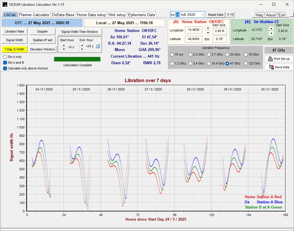
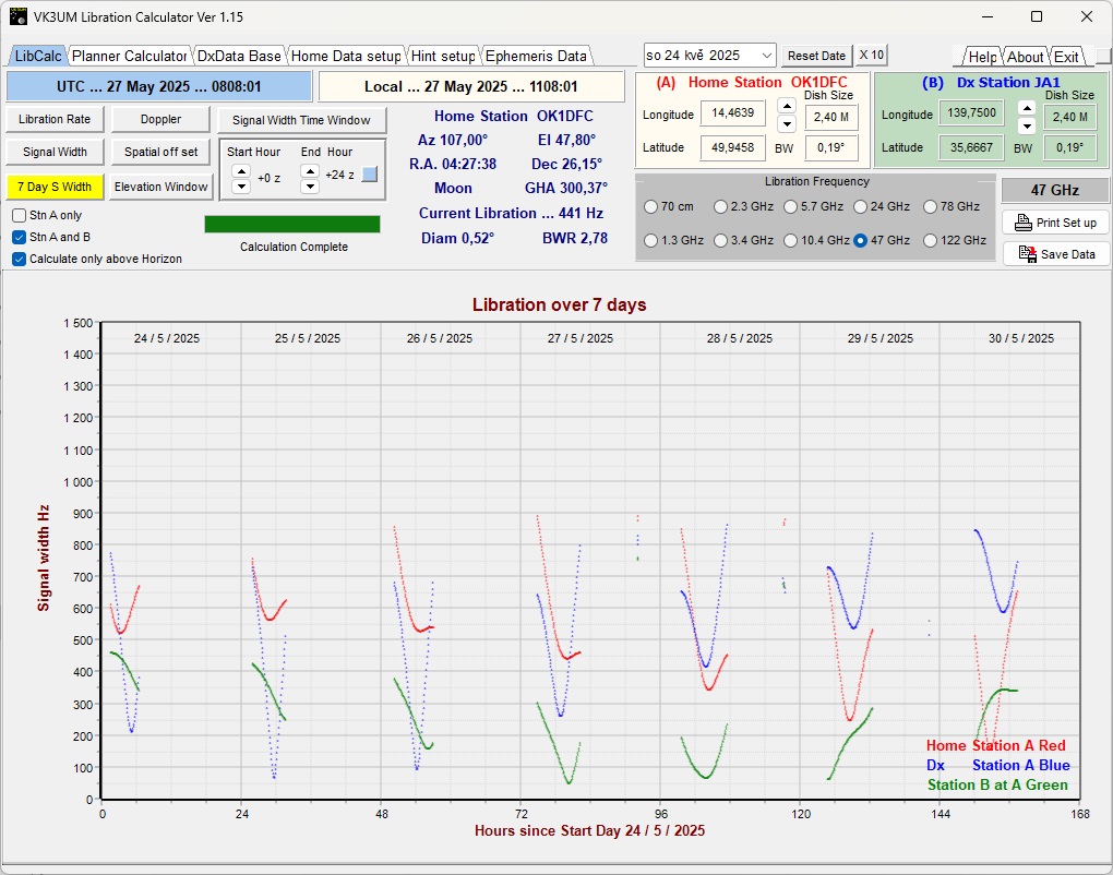
This figure shows the spread between OK and CT between May 24 and May 30, 2025. You can see that the optimal time for connecting CT and OK would be May 25 at 4:25 p.m., when the spread is only 57 Hz. Unfortunately, it was raining at that time and I was unable to install the TRV in the dish. The graph shows that even under the best possible conditions, the maximum spread is 600-700 Hz. This is essentially unusable in terms of the available power in the 47 GHz band. For interest, here are the graphs for the connection between JA and OK.
Since I could only be QRV until May 27, 2025, I chose the RW3BP station for my experiments. Sergej and I have known each other for thirty years, and since he has a well-equipped station, I expected to be able to decode or listen to him successfully. I didn't expect it to go so smoothly in the end, and I was very pleasantly surprised. After the first decoding of DL7YC last year, I made a few adjustments, but I didn't expect it to work this well.
RW3BP - Sergej

2.4 m offset dish from Polus. Equipment installed at the focal point. There is really no other option at 47 GHz.


The following images show details of the RW3BP device in the focus of the parabolic antenna. The image on the left is an overall view of the device for 47 GHz. As you can see in the other images, the “meat board” design is very popular among us, although there are also stations that have the entire device in a box. The image on the right is an image of the SSPA. It is a combination of two modules with a power of 16W and a total power at the feed of 30W. You may notice that Sergej does not use a waveguide switch for RX/TX, but switches between two feeds at the focus. This has its advantages. The bottom picture shows the VLNA connected directly to the feed.

Here is a graph showing the spread between OK and UA3. Sergey and I agreed on a frequency of 47088.100 CFOM, mode Q65-60E. This is currently the most suitable mode for working on this band. It can also be used advantageously in the 24 GHz band. And the time around 14:00 UTC. Since I am unable to transmit at the moment, but this will change very soon, Sergei called CQ and then called me by my call sign. The result is shown in the next picture.

So I decoded Sergei quite easily. I was even able to verify one of my theories about the Doppler shift during antenna pointing at the Moon. Yes, my antenna has a radiation pattern of only 0.16° in the 47 GHz band, so I can point it at the Moon. I have a total of three spots on the Moon with my antenna. When I point the antenna at the center of the Moon, you can see in the picture that the Freq, or the frequency I am decoding, is around 790 Hz, which corresponds to the agreed frequency. However, if I moved the antenna 0.2° ahead of the moon using the correction and started receiving the signal reflected from the right half, the level of the decoded signal decreased from -13, -15 dB to -18, -20 dB. This actually led to several decoding failures if I moved the antenna slightly ahead of the moon. If I had pointed the antenna to the left side, the frequency would have decreased exactly according to Doppler. So I verified in practice what I had theoretically assumed and what physics said should happen. But, as they say, “theory is gray, the tree of life is green.” At the end, you can see how Sergei started calling José EA3HMJ, who also decoded him without the slightest problem.
The following section contains several more pictures of other participants in the experiments. I will not go into detail here about things that are bothering me at the moment and are not entirely clear to me, but I will definitely return to the 47 GHz band before I start experimenting with the 76 GHz band.
CT1BYM - Miguel
Another station experimenting with the 47 GHz band is CT1BYM. Miguel borrowed an SSPA from Manfred DL7YC. The SSPA provides 15W of power and is constructed from four APN318 units. Miguel was therefore able to transmit during the last check day and established a connection with DL7YC and RW3BP.

This is what Miguel's “mass board” looks like. The green cylinder in the middle is the WR22 RX/TX switch, and to the left of it is the water-cooled SSPA.

Parabola at CT1BYM

Detail SSPA.

QSO CT1BYM and DL7YC, decoding also by RW3BP
DL7YC - Manfred
Manfred is QRV in the 47 GHz band with a 2.4 m diameter antenna, prime-focus. He uses a TWT system with 45 W output power as an amplifier. He is currently the strongest station and was also the first one I decoded in the 47 GHz band. Here are a few pictures of Manfred's setup.

2.4 m parabolic dish and TWT with TRV at the focal point of the dish.


Series of images DL7YC. Feed horn for 47 GHz, TWT in focus. The power supply is located under the dish in a waterproof box. To date, Manfred has made contact with DC7KY, RW3BP, JA1WQF (the first EU-Asia), as we wrote elsewhere, VE4MA and CT1BYM.
Other stations
EA3HMJ - José

LZ4OC - Saša

PE1EHG - Hans

EB3FRN - Iban

PE1CKK - Hans

IZ0JNY - Ivan
