|
PTT Sequencer |
|
Sequencer 1st generation 2008 - ALC power
supply separately |
|
|
Block
diagram
Timing
diagram how I am using that
Schematic
diagram and PCBs |
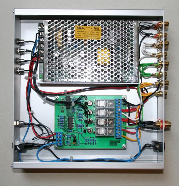
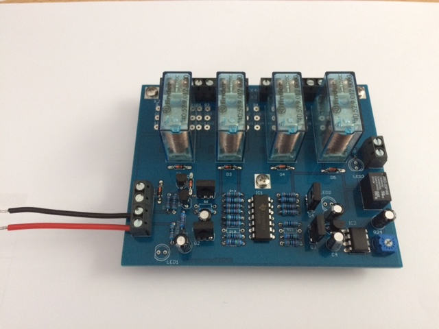
| View to open box with sequencer.
Switching PS 230V/15V-4,5A supporting Relays in antenna, PAs, LNAs. Relay
in each position is possible to setup for switching to ON or OFF,
according of request. Also on the PCB is possible to choice if relay on
PCB is in ON or OFF position. This solution giving lot of possibilities. |
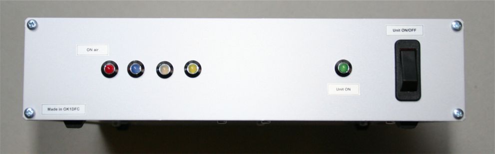 |
Front panel with control LED diodes.
Last in row from left is read LED diode and showing total PTT is position
ON AIR |
|
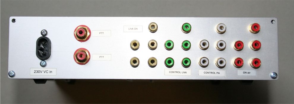 |
Rear panel with 230V socket
and two RCA connectors. One of them for PTT by grounding, second one for
PTT present by TTL or +12V on. Four different color RCA connectors for ANT
relay
- yellow, LNA-green, PAs - white, PTT of TRV & TRX - red. |
| |
|
|
Sequencer 2nd generation 2018 |
|
 |
 |
|
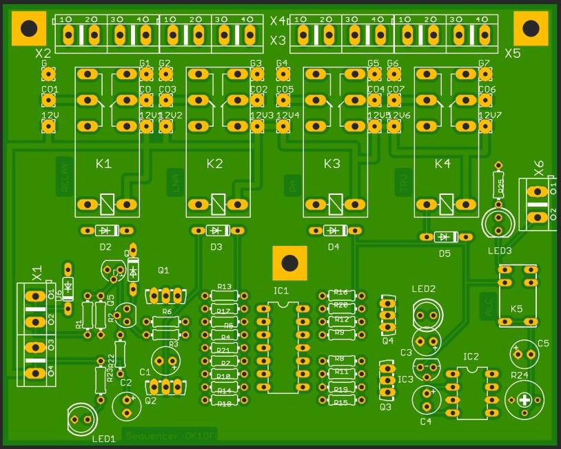
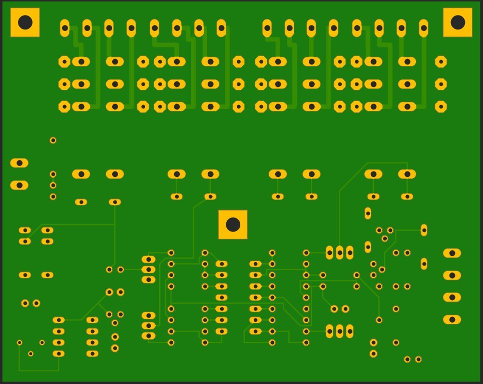
TOP view of PCB |
Bottom view of PCB |
|
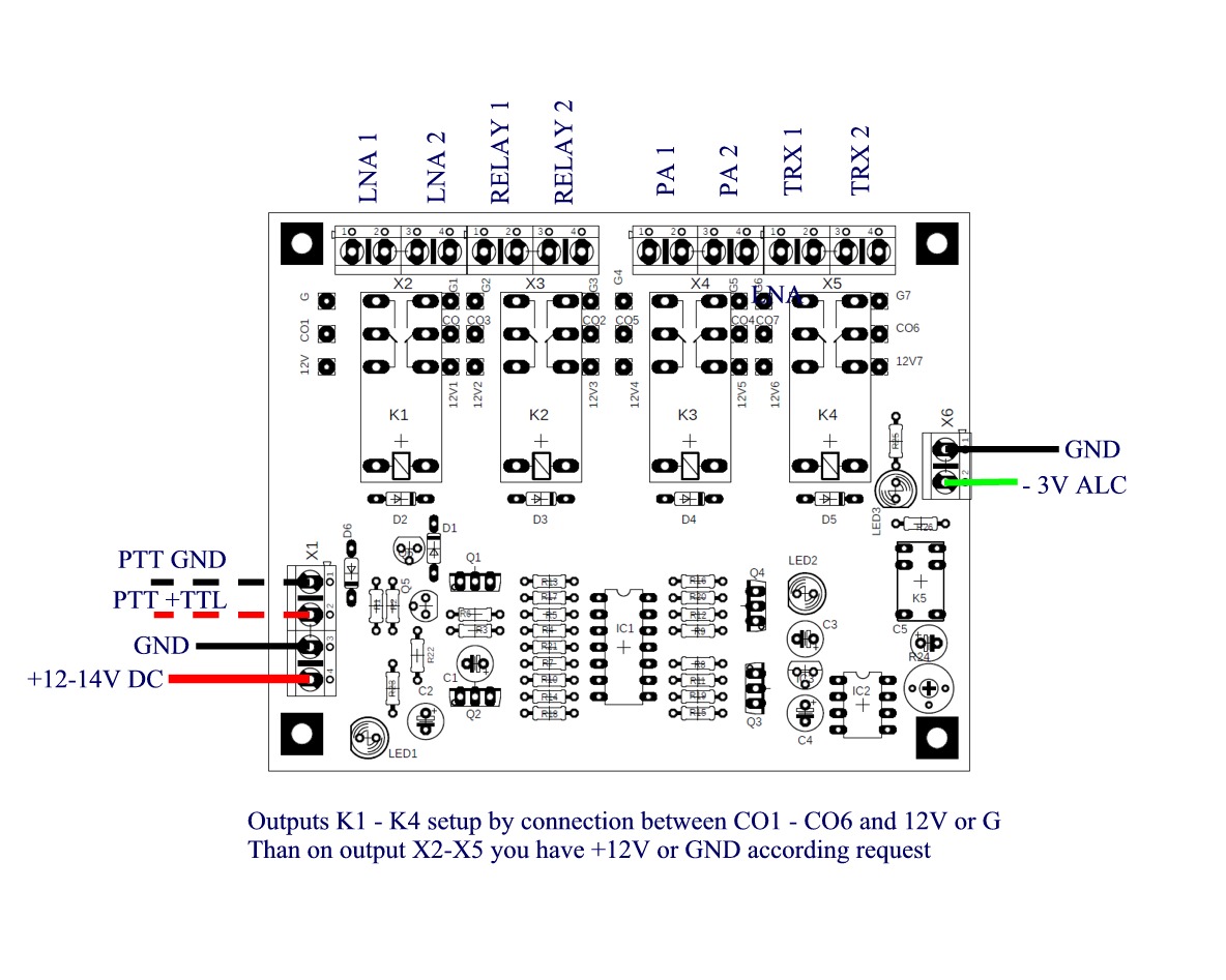
Sequencer schematics
|
|
2nd generation of my sequencer including also negative
power supply for protecting TRV trough ALC connection in to TRX. During RX
period is -3V presented on ALC input in transceiver. First, you never have
problem with spikes or peaks, second, you can squeeze CW Key or Mic, but TRX
has zero RF on the output. |
|
|
BACK to
MAIN PAGE |
|
|