47 GHz RX test TRV
Today, 13th of July, I finally finished after 6 month of work my 1st. the 47 GHz version of the TRV for EME and at early morning and day of Monday could perform its RX test. TX test will still wait, 10W SSPA is not quite the cheapest issue and the existing 130mW is not enough :-).
When I finished the device for the 24 GHz band, made the first EME connection and implemented EME expeditions 4U1ITU and SP0VHF, I thought it was the last band that I want to try on EME. It took a total of about a year, when I was devoured by a worm of curiosity, as it would be with the 47 GHz band. I didn't know that, for the first time, I'd start over from scratch. Everything was new and brought changes to the existing antenna system.
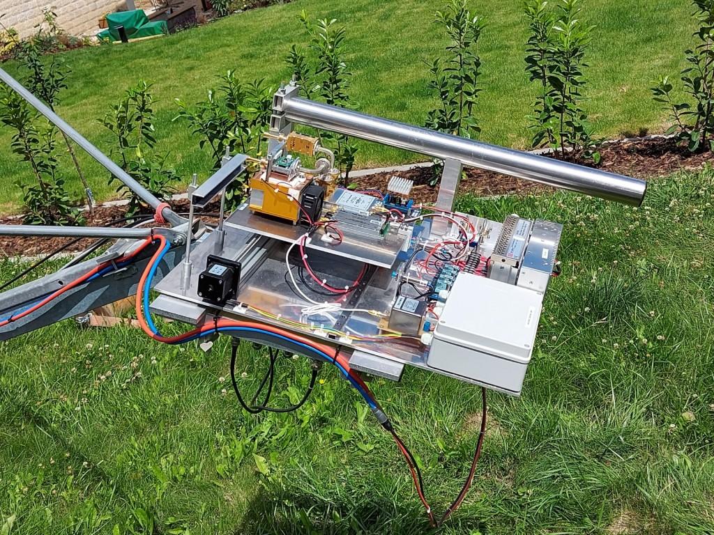
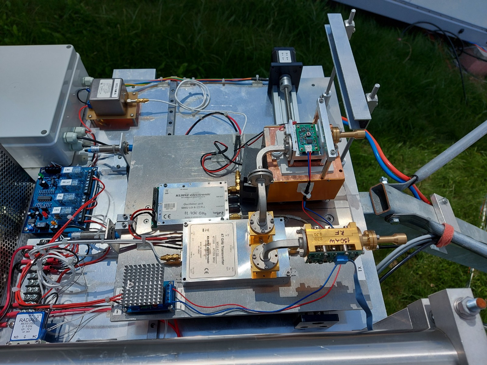
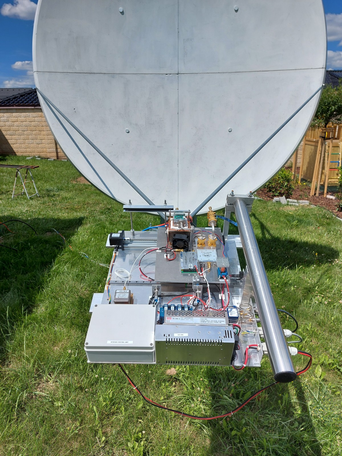
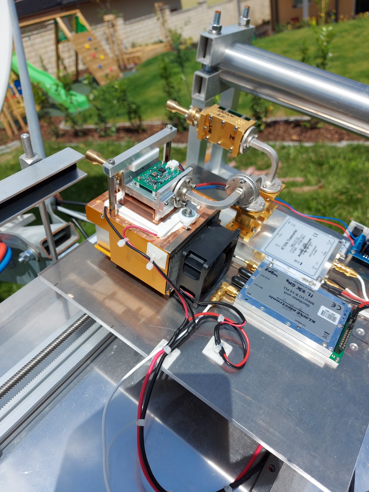
Device: As a device I used already a classic, the transverter from DB6NT and the programmable oscillator that is suspended on the double temperature stabilized TCXO 10 MHz. The device gives 70mW of power and the noise figure is 5dB N/F. To be able to work with the device and its construction, and also because experiments on this band can only be done in good weather, I chose the construction of a "meat board". This is one Aluminum plate 6mm thick with dimensions of 500×600mm. This plate is placed in the focus of the dish and on it all parts of the device are located. The structure can be seen in Figures 1, 2 and 3.
Dish and pointing of dish: This is a separate chapter and probably for a much longer talk. I will limit itself to the fact that thanks to the beaming angle of the offset dish with a diameter of 2,4 m = 0,18°, the sun does not appear only as a point, but can be run over in such a way that it looks like the antenna is not moving. The sun is already a wide enough object. In the pictures there is also a hot spot of the sun from EA3HMJ with pieces on a scale of 0.15°, so you can see how the sun is already wide on this band. Another thing is that if the antenna is really top-notch, it is that it will geometrically correspond to the 47 GHz band, it should have a theoretical gain of 60.8dBi at a beam width of 0.18°. According to the calculation according to VK3UM, I should therefore have a Sun noise of 12,24dB and not 7,7dB and a Moon of 2,3dB and not 0.77dB as I measured. So what's the problem? Uniquely in the shape accuracy of a fiberglass mirror, which has an integrated mesh of 1.5×1.5mm. If you calculate the wavelength for 47 GHz, it is 6mm, the lambda/4 is 1.5mm and we are at the problem. The mirror would need to be glued with aluminum foil. I didn't want to do that, so I was looking for so long until I got a 2.6m offset dish from one piece, aluminum, made of 5mm thickness. So I sold the existing antenna and bought this new one and started building a new mast, turning and tilting to fit within a tolerance of 0.01°. So again everything from the beginning HIHI. What EME system it is already, not even counting :-) The premise of putting the new dish into operation is September, so that in the autumn, when the conditions on the EME are in this band, I can already test the device to receive the via Moon signal.
VLNA: I did not deal with the preamplifier, I do not have options on bonding chip sets 1.5×2,5mm and so helped friends in Japan. Big thanks goes to Mitsuo JA1 WQF. My VLNA for 47 GHz has 2.4dB N/F and 24dB gain. Details on my site if you want to see more details, including cooling Peltier's cell.
Feed horns: Here I stayed with the classic for offset parabolas with W2IMU design. I just asked for help Mirek OK2AQ, if he could simulate me for a given feed radiation diagram, to knew how to do with the dish and whether there is still need to finish the collar or chock. Again, everything is to be seen on my site.
SSPA: This is a long run, the premise is 10W RF out, but more I write up to take a little forward.
RX/TX switch: There are WR22 waveguide switches, but their price starts at the flea market at 1000 USD and I don't even talk about the price from the manufacturer, so you don't think I was looking at the car catalog. So I decided to solve the switching by mechanical means and without attenuation. The WR22 switch with the appropriate waveguides brings a 0.5dB or more attenuation and is again a problem with the N/F preamplifier. What you work hard, you lose in the signal supply. If you want to see how it works, there's a small video on YouTube.
Measurement results 13.07.2020
Moon noise = 0.77dB
Sun noise = 7,7dB
VLNA N/F = 2,4dB – 20dB gain
Moon noise measurement conditions – Clear sky, elevation 25°- Temperature +8°C – Humidity 46%
Sun noise measurement conditions – Clear sky, elevation 25°- Temperature +14°C – Humidity 53%
I hope to be QRV soon and will have chance to test RX performance with some EME signals.
|
|
|
|
|
|